Markers > Connectors
FusionMaps also allows you to connect any two defined markers on the map using Marker Connectors. You can show custom labels for the marker connectors, link it to external URLs, show tool tips for the connector and customize all the cosmetics. Here, we'll see how to define and use marker connectors.
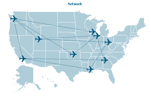
Shown below is an example of marker connectors where we've defined a few cities on the US Map and then connected them using connectors:

As you can see above, we've defined a few cities as markers and used the image marker feature to show a plane icon for each of them. Thereafter, we've connected the markers using connectors.
The following XML drives this map:
<map showShadow='0' showBevel='0' showMarkerLabels='0' useHoverColor='0' showLabels='0' showCanvasBorder='0' mapRightMargin='0' fillColor='AFCED9' bordercolor='FFFFFF' markerBgColor='00577F' animation='1'
markerBorderColor='00577F' markerRadius='3' showTooltip='0' showMarkerTooltip='1'>
... Map Data here ...
<markers>
<definition>
<marker id='SE' x='35.34' y='50.56' label='Seattle' />
<marker id='CO' x=' 525.85' y='172.94' label='Columbus' />
<marker id='MA' x='444.94' y='119.34' label='Madison' />
<marker id='LA' x='81.86' y=' 257.89' label='Los Angeles' />
<marker id='SLC' x='163.79' y='156.76' label='Salt Lake City' />
<marker id='KC' x='383.25' y='183.05 ' label='Kansas City' />
<marker id='AT' x='508.66' y='267' label='Atlanta' />
<marker id='CH' x='467.19' y='139.56' label='Chicago' />
<marker id='OK' x='344.82' y='236.65' label='Oklahoma City' />
<marker id='NO' x='432.81' y='314.53' label='New Orleans' />
</definition>
<shapes>
<shape id='Icon' type='image' URL='Resources/PlaneIcon.gif'/>
</shapes>
<application>
<marker id='SE' shapeId='Icon' />
<marker id='SP' shapeId='Icon' />
<marker id='CO' shapeId='Icon' />
<marker id='MA' shapeId='Icon' />
<marker id='LA' shapeId='Icon' />
<marker id='SLC' shapeId='Icon' />
<marker id='KC' shapeId='Icon' />
<marker id='AT' shapeId='Icon' />
<marker id='CH' shapeId='Icon' />
<marker id='OK' shapeId='Icon' />
<marker id='NO' shapeId='Icon' />
</application>
<connectors>
<connector from='SE' to='SLC' toolText='Seattle - Salt Lake City: 689 miles' dashed='1' color='00577F' alpha='40'/>
<connector from='CH' to='AT' toolText='Chicago - Atlanta: 606 miles' dashed='1' color='00577F' alpha='40'/>
<connector from='SE' to='LA' toolText='Seattle - Los Angeles: 954 miles' dashed='1' color='00577F' alpha='40'/>
<connector from='AT' to='LA' toolText='Atlanta - Los Angeles: 1946 miles' dashed='1' color='00577F' alpha='40'/>
<connector from='LA' to='NO' toolText='Los Angeles - New Orleans: 1645 miles' dashed='1' color='00577F' alpha='40'/>
<connector from='KC' to='MA' toolText='Kansas City - Madison: 381 miles' dashed='1' color='00577F' alpha='40'/>
<connector from='SE' to='OK' toolText='Seattle - Oklahoma City: 1499 miles' dashed='1' color='00577F' alpha='40'/>
<connector from='MA' to='SE' toolText='Madison - Seattle: 1595 miles' dashed='1' color='00577F' alpha='40'/>
<connector from='KC' to='SLC' toolText='Kansas City - Salt Lake City: 905 miles' dashed='1' color='00577F' alpha='40'/>
<connector from='SLC' to='CH' toolText='Salt Lake City - Chicago: 1239 miles' dashed='1' color='00577F' alpha='40'/>
<connector from='CO' to='SLC' toolText='Columbus - Salt Lake City: 1575 miles' dashed='1' color='00577F' alpha='40'/>
<connector from='NO' to='CO' toolText='New Orleans - Columbus: 355 miles' dashed='1' color='00577F' alpha='40'/>
<connector from='OK' to='CH' toolText='Oklahomo City - Chicago: 682 miles' dashed='1' color='00577F' alpha='40'/>
</connectors>
</markers>
</map>
Here, we first define the properties of map as attributes of <map> element. Then, we define the data for the map (which has been intentionally omitted in the XML above).
Soon after that, we first define our custom markers for the map and apply them. As previously explained, each marker has its id, x, y and label. Also, we use an image marker shape to show each marker on the map.
The newly introduced element in this XML is the <connectors> element. As children of this element, you'll find multiple <connector> element - one for each connector on the map. Each connector element helps you connect two defined markers on the map. To define which connectors to connect, you specify the marker ID as:
<connector from='From_Marker_ID' to='To_Marker_Id' .../>
You need to make sure that the marker IDs specified in <connector> element is defined in the XML.
Additionally, we've defined the toolText for each connector and specified a few cosmetic properties here.
Each <connector> element can have the following attributes:
| Attribute Name | Type | Range | Description |
| from | String | Id of the marker from where the connector will start. | |
| to | String | Id of the marker where the connector will end. | |
| link | String | Each connector can also link to an external URL. For this attribute, you can specify the link for the connector in FusionCharts Link format. | |
| label | String | Each connector can have a visible text label. This attribute lets you set the text. | |
| toolText | String | If you want to set a custom tool text for the connectors, this attribute lets you do so. | |
| thickness | Number | 0-10 | Thickness of the connector line. |
| color | Color | Hex Code | Color of the connector line. |
| alpha | Number | 0-100 | Alpha (transparency) of the connector line. |
| dashed | Boolean | 0/1 | Whether the connector line should appear as dashed? |
| dashLen | Number | 0-10 | If the connector line is to appear as dashed, this attribute defines the length of each dashed line. |
| dashGap | Number | 0-10 | If the connector line is to appear as dashed, this attribute defines the gap between each dashed line. |